Sfd Bmd Formula : Sfd And Bmd For Simply Supported Beam With Udl - The Best ... - According to bis, the standard symbols used for sketching sfd are point load.. It will be opposite.positive bm: And shear force diagram s.f.d. Sfd will tell you the variation of shear force along the length of the beam and bending moment diagram i.e. Bmd = bending moment diagram e = modulus of elasticity, psi or mpa i = second moment of area, in 4 or m 4 l = span length under consideration, in or m Keeping a consistent sign convention is extremely important!
3 kn/m 4 m a b example 8. As we know very well that shear force diagram i.e. The external and internal diameters of the hollow cast iron column are 5cm and 4cm respectively. Somewhere on the beam,combination of point loads and u.d.l. Sfd & bmd shear force & bending moment diagram 1.
Sfd Bmd Formula / Cantilever Beam Point Load At Free End ... from image.slidesharecdn.com As we know very well that shear force diagram i.e. It will be opposite.positive bm: The final diagrams in such cases will be an assembly of sfd and bmd of all structural elements of the frame. Setting the bending diagrams of beam. Bending moment diagram shape and curvature calculator for ers bending moment and shear force cantilever beam with varying load on full span calculator for ers slope and deflection simply. Stress and moment value and where it is located. Bending moment diagram (bmd) shear force diagram (sfd) axial force diagram. Sfd, bmd for cantilever beams, simply supported beams and periyar centenary polytechnic sem sy.pdfconstruct sfd and bmd.
Draw the shear force v and bending moment m diagrams for beams shown below study.
Axial, shear, and bending moment diagrams (afd, sfd, and bmd) show the internal forces and moments along a structural member. Of a cantilever beam having point load at the end,several point loads,u.d.l. As we know very well that shear force diagram i.e. A r by 3 kn/m 4 m b m b by taking the moment at b: 63 sfd bmd 30kn 10kn 50kn parabola x = 1.5 m parabola 20knm 10knm point of contra flexure bmd cubic parabola 20knm. 2)for uniformly distributed load load(udl) the degree of curve is 1st(linear) in sfd and 2nd. Jahangirabad instiute of technology barabanki department of mechanical engineering elements of mechanical engineering ravi vishwakarma 31/12/16 ravi vishwakarma 1 2. Not over the whole span,u.d.l. Today we will see here the basics of shear force and bending moment diagrams in subject of strength of materials with the help of this post. 0:41 i have mistakenly said sagging as hogging and hogging as sagging. Lesson 7 of 21 • 26 upvotes • 11:52 mins. Bending moment diagram (bmd) shear force diagram (sfd) axial force diagram. It is the unbalanced force on either side of a section parallel to cross section.
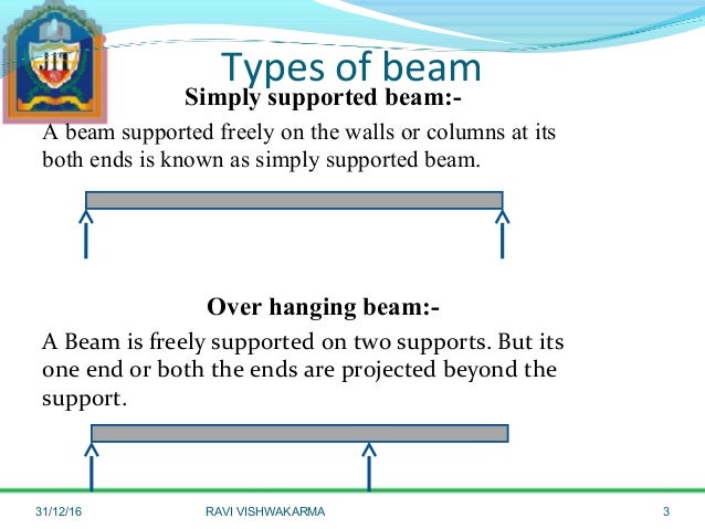
A simply supported beam is the most simple arrangement of the structure. Example on simply supported beam 7. 0:41 i have mistakenly said sagging as hogging and hogging as sagging. Also locate points of contra flexure if any. Of a cantilever beam having point load at the end,several point loads,u.d.l.
SFD and BMD for Simply Supported beam (udl and point load ... from i.ytimg.com 3 kn/m 4 m a b example 8. Fig:4 sfd and bmd for simply supported at midspan udl carrying beam. It will be opposite.positive bm: 2)for uniformly distributed load load(udl) the degree of curve is 1st(linear) in sfd and 2nd. A r by 3 kn/m 4 m b m b by taking the moment at b: Keeping a consistent sign convention is extremely important! Somewhere on the beam,combination of point loads and u.d.l. Learn vocabulary, terms and more with flashcards, games and other study tools.
And shear force diagram s.f.d.
Numerical on sfd and bmd on simply supported beams problems on simply supported beams. ∆ = deflection or deformation, in or m. By plotting the sfd and bmd you came to know what is the max. Sfd (kn) bmd (knm) calculate the shear force and bending moment for the beam subjected to the loads as shown in the figure, then draw the shear force diagram (sfd) and bending moment diagram (bmd). These values (especially max bending moment) are used as input for deciding the minimum cross sectional area required to withstand the loads (which you used for plotting the sfd and bmd). Of a cantilever beam having point load at the end,several point loads,u.d.l. 5 problems on lateral load analysis by portal method 1. Below are the beam formulas and their respective sfd's and bmd's; .(sfd & bmd) shear force diagram (sfd): A simply supported beam cannot have any translational displacements at its support points, but no restriction is placed on. Shear force bending moment 4. But here we explain the formulas. Sfd & bmd, shear force diagram and bending moment diagram, sfd, bmd notes.
63 sfd bmd 30kn 10kn 50kn parabola x = 1.5 m parabola 20knm 10knm point of contra flexure bmd cubic parabola 20knm. A simply supported beam cannot have any translational displacements at its support points, but no restriction is placed on. 45 draw sfd and bmd for the single side overhanging. According to bis, the standard symbols used for sketching sfd are point load. And shear force diagram s.f.d.
SFD and BMD - Problem 1 Hindi Shear Force and Bending ... from i.ytimg.com A simply supported beam is the most simple arrangement of the structure. Bending moment diagram (bmd) shear force diagram (sfd) axial force diagram. Setting the bending diagrams of beam. Axial, shear, and bending moment diagrams (afd, sfd, and bmd) show the internal forces and moments along a structural member. We are going to define the positive… And shear force diagram s.f.d. Shear force bending moment 4. Sfd and bmd for a simple beam with a uniform load.
Hoggingin this video, i have dis.
Sfd_bmd #sfd_bmd_continuous_beam hello friends, this video tutorial is on request of many people who wanted sfd and bmd: A r by 3 kn/m 4 m b m b by taking the moment at b: Sfd & bmd shear force & bending moment diagram 1. Shear force bending moment 4. Keeping a consistent sign convention is extremely important! Shear force and bending moment beam: Also locate points of contra flexure if any. Setting the bending diagrams of beam. 3 kn/m 4 m a b example 8. 63 sfd bmd 30kn 10kn 50kn parabola x = 1.5 m parabola 20knm 10knm point of contra flexure bmd cubic parabola 20knm. Lesson 7 of 21 • 26 upvotes • 11:52 mins. They help determine the material, size, and type of a member given a set of loads it can support without structural failure. Not over the whole span,u.d.l.
Learn more about @fem, @bmd, sfd bmd sfd. A simply supported beam cannot have any translational displacements at its support points, but no restriction is placed on.